Broadband Hexbeam - Basics
1. Introduction
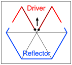
This section of the website describes the new Hexbeam design which I developed in the Autumn of 2007. It was the subject of an article I wrote for the December 2007 edition of Antennex - the on-line magazine for antenna experimenters. The unique feature of the new design is a revised shape of Reflector, shown on the right, which significantly extends the performance bandwidth and improves the SWR, at the cost of a 17" increase in turn radius on a 20m version. For clarity we refer to the new design as a "Broadband Hexbeam", and to the conventional design as a "Classic Hexbeam".
2. Performance
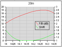
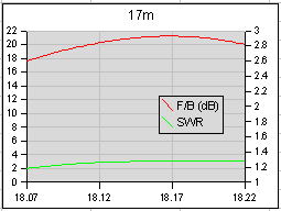
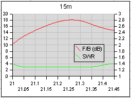
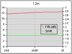
| HyGain TH11DX | G3TXQ Broadband Hexbeam | Cushcraft MA5B | |
| Peak Gain (dBd) 20m 17m 15m 12m 10m |
6.4 6.2 5.9 5.3 7.0 |
3.8 3.2 3.5 3.0 3.6 |
1.5 -1.1 2.7 -1.1 3.2 |
| Peak F/B (dB) 20m 17m 15m 12m 10m |
27 22 25 15 19 |
22 19 16 13 16 |
22 0 12 0 10 |
| 2:1 SWR B/W (kHz) 20m 17m 15m 12m 10m |
350 100 450 100 1200 |
350 <1.7 100 <1.2 450 <1.4 100 <1.7 1400 |
90 100 255 110 665 |
| Turn radius (ft) | 22 | 10.7 | 8.8 |
| Weight (lbs) | 88 | 131 / 22 | 26.5 |
| Wind area (sq ft) | 12.5 | 6 | 3.2 |
| Price2 | £1000 | £1203 | £370 |
| 1 Using lightweight fishing poles rather than fibreglass tubing 2 UK prices July 2008 3 Approximate cost of parts |
|||
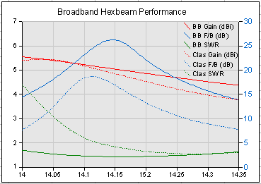
The chart on the right shows how the Broadband Hexbeam compares with a Classic Hexbeam on 20m, and the table shows how the performance of the Broadband Hexbeam stacks up against a couple of popular commercial 5-band HF beams - the comparably sized Cushcraft MA5B and the much larger, "full size", HyGain TH11DX
Here are some audio clips which demonstrate the F/B performance of the new design. They comprise 3-5 seconds with a beam pointed towards a DX station, interlaced with 3-5 secs with a beam pointed in the opposite direction. Interestingly, analysis of the audio waveforms suggests that the F/B ratios are in excess of 30dB - a higher figure than I measure with a line-of-sight source on my test range.
Hexbeam F/B 20m Iceland
Hexbeam F/B 20m USA
Hexbeam F/B 17m USA
Hexbeam F/B 17m USA
Hexbeam F/B 20m USA
Hexbeam F/B 20m USA
Hexbeam F/B 20m USA
And here is a clip demonstrating the difference between my Broadband Hexbeam at 20ft and my 132ft inverted V doublet with its centre at 20ft. The first half of each 10 second period is the Doublet and the remaining period is the Hexbeam. A half second gap has been inserted to emphasise the changeover.
3. Design details
| 20m | 17m | 15m | 12m | 10m | |
| Driver (half-length) | 218" | 169.5" | 144.5" | 121.7" | 106.8" |
| Reflector (total) | 412" | 321" | 274.4" | 232" | 204.4" |
| End spacing | 24" | 18.5" | 16" | 13.5" | 12" |
| Vertical spacing from 10m elements | 38" | 15" | 9" | 5" | 0 |
This table shows the recommended dimensions for a 5-band Broadband Hexbeam constructed from #16 or #14 bare copper wire. The band feedpoints are interconnected with 50 Ohm coax, and the array is Top fed.
This 5-band design requires a horizontal distance of about 130" from the Centre Post to the tips of the spreaders. If you are unable to accomodate this increased size, don't be tempted to stick to the smaller Classic shape for 20m and adopt the new shape for 17m thru 10m: modelling shows that the 20m performance bandwidth suffers dramatically, probably due to the mid section of the 17m Reflector providing an RF coupling path between the "knees" of the 20m Reflector.
Although this site contains some photographs of my own Broadband Hexbeam, it does not provide detailed constructional information. If you need guidance on making one, you should visit Leo's (K4KIO) website where you will find excellent step-by-step instructions. Max-Gain Sytems in the USA also do a complete kit of fibreglass tubing for the Broadband Hexbeam.
The design has now been adopted by a significant number of constructors, and these dimensions are proving to be robust and repeatable. WY3A, is one such constructor who is now enjoying the fruits of his labour - take a look at Bill's website and the photographs of his G3TXQ Broadband Hexbeam.
| 30m | 40m | |
| Driver (half-length) | 306" | 438" |
| Reflector (total) | 578" | 828" |
| End spacing | 34" | 48" |
A number of constructors have enquired about dimensions for 30m or 40m versions of the antenna; they are shown in the next table. They assume the antenna is constructed from #16 gauge bare copper wire, and that connector blocks are used to join the wire elements to the tip-spacing cords. Please note that these dimensions are the result of computer modelling exercises - I have not yet built antennas to confirm them.
4. Background
A consequence of the Classic Hexbeam's geometry is a relatively narrow performance bandwidth; typically the F/B exceeds 10dB over a band equivalent to only 1.4% of the centre frequency, and the SWR is above 2:1 for a significant proportion of this band. This narrow bandwidth is largely determined by the Q of the Reflector which I measured at about 30 for a 10m element constructed from #16 wire. Compare this with a linear dipole which has a Q of about 10. I reasoned that if I could find a way of reducing the Q I should end up with a broader-band antenna.
I spent many hours modelling Reflectors and evaluating ideas on a 10m testbed - you can see the detail on the Reflector Experiments page. I tried using thicker wire of various types, including 2 varieties of coaxial cable and "caged" wires. I also tested alternative Reflector shapes. Of all the ideas evaluated, by far the most effective and easiest to implement was to change the shape of the Reflector. Even when using relatively thin #16 wire the new shape has a radiation resistance of 44 Ohms and a Q of about 17. It requires an increase in turning radius of about 15%. Modelling a Hexbeam with this geometry produced very encouraging results: F/B > 10dB and SWR < 2:1 across all of the 20m, 17m, 15m and 12m bands, and approximately 1 MHz of 10m. The modelling suggested there was little to be gained by making the same change to the shape of the Driver element; in fact, retaining the classic shape for the Driver delivers a better match to 50 Ohms and avoids a further increase in the turning radius.
Constructing and testing a 10m monoband version of the new antenna confirmed the modelling results, and so a full 5-band test beam was constructed. The 20m, 17m and 15m results were immediately satisfactory, but it took some time to optimise the 12m and 10m performance; the proximity of these bands often causes problematic interactions which are not always predicted by the modelling, and the final wire dimensions for these bands were a result of "cut and try" on the testbed.
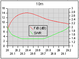
The following charts show the measured performance of the 5-band prototype with the baseplate at a height just under 20ft. At this height, ground reflections cause the 10m and 12m peak F/B figures to be suppressed compared to the Free Space values, and the 20m and 17m figures to be enhanced.
