Classic Hexbeam - Tuning
1. Why do we need to tune the Classic Hexbeam ?

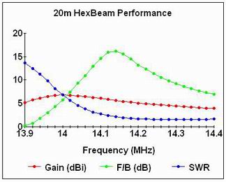
We saw from the Classic Hexbeam - In depth page that the antenna is relatively narrow-band; for example our 20m benchmark antenna delivers >10dB F/B performance over a bandwidth of about 200KHz - that's 1.4% of centre frequency. It is important therefore that we tune the antenna to make sure this region of useful performance coincides with where our operating interests lie, particularly on 20m, 15m and 10m where it represents only 56%, 65% and 23% respectively of the amateur band. Forward Gain is less frequency-dependent and is not so much of an issue.
You can see from the chart on the right that the F/B performance is "skewed" - it falls off more slowly at higher frequencies than at lower frequencies - so a good "rule of thumb" would be to tune the antenna for best F/B about one third the way into the band of frequencies of interest.
You can, of course, simply build a Classic Hexbeam to recommended dimensions and hope that it is tuned correctly. However many factors affect the tuning - reflector length, wire size and type, height above ground etc - and my advice would always be to tune the antenna (or at least check its tuning) in your local environment.
2. How do we tune it ?

We saw earlier that it is the length of the Reflector that primarily determines the frequency of maximum F/B. So, tuning the HexBeam is a matter of trimming the Reflector until the peak F/B occurs at the frequency you require; be sure to trim the two halves of the Reflector by equal amounts.
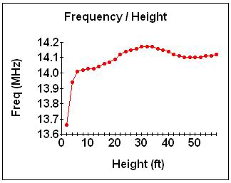
Antenna tuning is affected by height above ground, so ideally we would make adjustments with the beam at its final height and in its final environment. However this is not always possible and we often have to tune at lower heights, "aiming off" for the shift in frequency we expect when it is raised. This second chart illustrates the way the resonant frequency of a 20m Reflector varies with height above ground; it could be used for other bands by re-labelling the horizontal axis in terms of Wavelength, and scaling the frequency axis according to the band. From the chart you can see that it would be inadvisable to tune the antenna much below 10ft - the aim off would be large and difficult to determine accurately.
Checking that the antenna is delivering peak F/B at the desired frequency is a challenge for most Hexbeam builders, who typically do not have the facilities to measure F/B accurately. Fortunately, there are several other Classic Hexbeam parameters that can be measured relatively easily which pinpoint the frequency of peak F/B quite reliably.
On a 20m Classic Hexbeam, which had a peak F/B at 14.135 MHz, I measured the following parameters:
- Reflector resonance - zero reactance [14.129 MHz]
- Minimum Reflector SWR [14.154 MHz]
- Maximum Reflector current [14.127 MHz]
- An SWR which is 1.4 times the minimum SWR [14.137 MHz]
As you can see, we could use any one of these parameters as a way of determining the frequency of best F/B and not be in error by more than 20 KHz - close enough for all practical purposes. We will now look at how to measure each of these parameters in practice:
a) Reflector Resonance
Reflector resonance is measured by connecting an antenna analyser between the two halves of the Reflector and finding the frequency at which the reactance is zero. The Driver must be open circuit at its centre when making this measurement, otherwise you will be finding the resonance of the composite beam rather than just the Reflector.
You also need to compensate for the impedance transformation that will occur if there is any significant length (> 2.5") of connecting lead between the analyser and the Reflector. One solution is to cut the connecting lead to a multiple of a half wavelength, in which case the impedance seen at the analyser will be the same as the impedance at the Reflector; or you will need to calculate the Reflector impedance from the analyser measurement. Take a look at my Antenna Impedance Measurement page for details on how to do this.
In either case I would advise that you calibrate the connecting lead by terminating it with a known load - say a 100 Ohm resistor - in place of the Reflector, and check that you get the expected [100 + j0]result from your measurements.
b) Minimum Reflector SWR
Connect an antenna analyser (or exciter through an SWR meter) across the centre of the Reflector. The Driver must be open circuit at its centre when making this measurement, otherwise you will be measuring the SWR of the composite beam rather than just the Reflector. You can connect through any convenient length of 50 Ohm coax. Find the frequency at which the SWR is minimum.
In practice this can be quite difficult to do because the Reflector SWR minimum is very "flat". One solution, if you are using an analyser and can therefore tune outside the amateur band, is to note the two frequencies either side of the minimum where the SWR is, say, 4:1 and assume the minimum is mid-way between them.
c) Maximum Reflector current

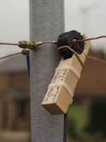
This option assumes that you have a "clip-on" current probe which will operate at HF frequencies. You can see details of the one I use on my Milliwatt Meter page; the photo on the right shows it in action.
Apply low power to the Driver - if the meter is sensitive enough you will find that the output from a signal generator or antenna analyser will be sufficient. Make sure the two halves of the Reflector are linked, and clip the current probe across a Reflector wire close to the centre post. Now sweep the generator and determine the frequency at which maximum current flows in the Reflector.
d) SWR 1.4 times minimum
This option is probably the easiest to implement and delivers surprisingly good accuracy. The principle behind the technique is that, at the frequency of best F/B, the SWR is significantly higher than its minimum value. Modelling, backed up by practical measurements, shows that it is a reliable indicator of beam tuning for a wide range of Hexbeam SWR curves. Do not try to use this option if you have implemented any antenna matching - the matching will have changed the shape of the SWR curve and with it the underlying premise on which the technique works.
Make sure the two halves of the Reflector are linked, and apply power to the Driver through an SWR meter, or connect it to an antenna analyser. Slowly sweep the frequency until you find the minimum SWR; note this minimum SWR value - the frequency is not important. Now lower the frequency until the SWR begins to rise, and locate the frequency where the SWR has risen to 1.4 times the lowest value noted earlier. If you find that there is more than one minimum, work from the lowest frequency one.
When you have determined the frequency of best F/B by one of these methods you can assess whether or not to make any adjustments. You can use the "rules of thumb" developed in the section on "Reflector length" to gauge how much to trim or add:
- 20m - 68KHz/inch
- 17m - 107KHz/inch
- 15m - 145KHz/inch
- 12m - 202KHz/inch
- 10m - 256KHz/inch
or use the formula: (new length) = (oldlength) x (old frequency) / (new frequency)

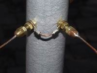
It's a lot easier to shorten wires than lengthen them, so you might want to begin the tuning process with Reflectors that are deliberately long. Many Hexbeam builders (me included) terminate the two halves of the Reflector on separate connections at the centre post and use a short link to join them (see photo); this is handy if you cut too much off during the tuning process - to compensate you just make the link a bit longer, rather than having to solder short lengths of wire onto the Reflector ends!
Finally, make the same dimensional changes to the Driver that you have made to the Reflector so that you retain the original Reflector / Driver ratio.