Hexbeam multiband tuning (Part 1)

We saw in other sections that, compared to a full-size 2-element Yagi, Hexbeams are relatively narrow-band antennas - particularly the Classic version which needs to be tuned to deliver best performance at the frequencies which interest you. We will look in this section at how the tuning is affected when several band elements are brought together to form a multiband Hexbeam.
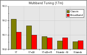
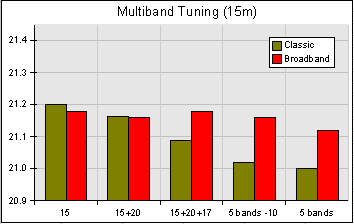
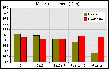
Shown below are tuning data charts for a 5 band (20m thru 10m) Broadband Hexbeam and a Classic Hexbeam. On each chart the extreme left-hand data is the frequency of best F/B ratio for the monoband element; the data to the right then shows progressively how the tuning changes as further band elements are added to the structure.
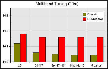
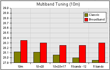
These data lead to the following conclusions:
- the tuning of all bands is affected to some degree when extra wires are added for other bands;
- with some exceptions, the general trend is for the frequency to drop as extra bands are added;
- the bands closest (in physical separation and in frequency) tend to have the greatest de-tuning affect;
- although the charts do not show it, the modelling which led to this data indicates that it's the proximity of neighbouring Reflectors (rather than the Drivers) that has most influence on the tuning;
- the Broadband Hexbeam tuning is affected significantly less than the Classic Hexbeam, so 5-band wire dimensions should work well on other Broadband arrays, including monoband versions.
It is probably unnecessary to tune a Broadband Hexbeam "in situ" because:
- its wider bandwidth makes it more immune to tuning errors;
- its lower "Q" Reflector makes it less affected by adjacent wires;
- the absence of any terminals at the centre of the Reflector removes any chance of ambiguity in wire lengths;
However, it is highly recommended that the Classic Hexbeam be tuned as described below.
The complexity of the interactions between the wires for the various bands makes it unrealistic to load the wires for one band onto the structure and "aim off" while tuning it to allow for the changes that will occur when other bands are added. I would strongly advocate loading all wires - Drivers and Reflectors - before beginning the tuning process. The objective is to get the antenna close to its final form so that as many of the interactions as possible are being taken into account.
We saw on the Classic Hexbeam - In depth page that tuning the antenna is a matter of trimming the Reflector until the peak F/B occurs at the frequency we require; and we must remember to trim the two halves of the Reflector by equal amounts. Any of the 4 tuning techniques described on the Classic Hexbeam Tuning page can be used succesfully on a multiband array, but note the following:
a) Reflector Resonance
- The band interconnecting links must not be in place.
- All Reflectors not being tuned must have their two halves linked.
- The Driver of the band being tuned must be open-circuit at its centre.
- All other Drivers must have their two halves linked - preferably by a 47 Ohm resistor.
b) Minimum Reflector SWR
- The band interconnecting links must not be in place.
- All Reflectors not being tuned must have their two halves linked.
- The Driver of the band being tuned must be open-circuit at its centre.
- All other Drivers must have their two halves linked - preferably by a 47 Ohm resistor.
c) Maximum Reflector current
- The band interconnecting links can be in place.
- All Reflectors must have their two halves linked.
- The signal source is connected to the composite array feedpoint.
d) SWR 1.4 times minimum
- The band interconnecting links may be in place, although results are likely to be more accurate if you can omit them at this stage.
- All Reflectors must have their two halves linked.
- The Driver of the band being tuned is connected to the signal source.
- All other Drivers must have their two halves linked - preferably by a 47 Ohm resistor.
- If you have chosen to tune with the interconnecting links in place, connect the signal source to your final choice of feedpoint and omit the 47 Ohm resistors.
Part 2 of this Multiband Tuning section looks in more detail at the frequency offsets caused on a Classic Hexbeam by the interaction of band elements, and develops a set of correction factors from which the dimensions of any HF multiband Classic Hexbeam array can be determined.