Small Hexbeams
The Hexbeam is already a small antenna - its turning radius being approximately half that of a full-size 2-element Yagi. It is therefore unreasonable to expect that it can be made even smaller without significant performance penalties. However there are a couple of scenarios where the performance penalty might be an acceptable trade-off for the reduction in size.
1. 20m Broadband in 20m Classic size
Some Hexbeam constructors who have already built a 5-band Classic design may wish to move to the Broadband design without modifying the support structure. Unfortunately, the simple option of retaining the Classic shape for 20m and converting to the Broadband shape for 17m through 10m does not work - the 20m Classic reflector is badly affected by the adjacent 17m Broadband reflector. The solution is to try to "shrink" the 20m Broadband shape into the same turning radius as the Classic shape.
 My work on coaxial antenna elements described elsewhere
on this website showed that, although loading an antenna using coaxial cable is likely to
be very inefficient, inductive loading using coils is viable. A design was developed using
EZNEC which delivers 20m Classic Hexbeam performance but uses the Broadband shape.
My work on coaxial antenna elements described elsewhere
on this website showed that, although loading an antenna using coaxial cable is likely to
be very inefficient, inductive loading using coils is viable. A design was developed using
EZNEC which delivers 20m Classic Hexbeam performance but uses the Broadband shape.
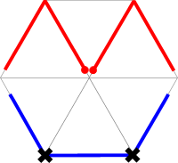
It uses two loading coils inserted into the reflector where the wire crosses the support spreaders - the positions marked with a black cross in the diagram. These positions were chosen partly because they provide good mechanical support for the coils, and partly because "off-centre loading" provides greater performance bandwidth than centre loading. The off-centre loading does cause some reduction in bandwidth but it is offset by the Broadband reflector shape; the net result is something close to Classic performance.
The dimensions for this design, using #16 bare copper wire, are:
- Driver "half-length": 218.5"
- Total reflector: 310.5"
- Driver to spreader end space: 7.5"
- Reflector to spreader end space: 15"
- Loading coils: 2.85uH [eg 9 turns on 1.5" diameter form occupying 1"]
- Radius: 113.5"
2. Small 30m Hexbeam
 There appears to be some interest in a directional antenna for 30m that can be fitted into
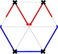
a modest space. The design shown on the right provides Forward Gain of 2-3dBd and a F/B of about
10dB in a turning radius of 133.5". Here, two loading coils are used in the Driver and two in the
reflector; once again they are placed off-centre where the wires cross support spreaders.
There appears to be some interest in a directional antenna for 30m that can be fitted into
a modest space. The design shown on the right provides Forward Gain of 2-3dBd and a F/B of about
10dB in a turning radius of 133.5". Here, two loading coils are used in the Driver and two in the
reflector; once again they are placed off-centre where the wires cross support spreaders.
The dimensions for this design, using #16 bare copper wire, are:
- Driver "half-length": 219"
- Total reflector: 410"
- Driver to reflector end space: 42"
- Driver loading coils: 9.1uH [eg 21 turns on 1.5" diameter form occupying 2"]
- Reflector loading coils: 5.45uH [eg 14.5 turns on 1.5" diameter form occupying 1.5"]
- Radius: 133.5"
 In order to gain confidence in these simulated designs, I built a
one-third scale experimental model
of the 30m design. I chose a turning radius of 47" which, extrapolating from the 133.5" of the
30m version, could be expected to produce a beam tuned to 28.8 MHz. I found that the Driver and
Reflector tuning could easily be checked by placing a dip meter close to the loading coils. As
expected, some adjustment of the
loading coils
was required to get the elements tuned to the required frequencies (Driver 29.1 MHz, Reflector
28.8 MHz).
In order to gain confidence in these simulated designs, I built a
one-third scale experimental model
of the 30m design. I chose a turning radius of 47" which, extrapolating from the 133.5" of the
30m version, could be expected to produce a beam tuned to 28.8 MHz. I found that the Driver and
Reflector tuning could easily be checked by placing a dip meter close to the loading coils. As
expected, some adjustment of the
loading coils
was required to get the elements tuned to the required frequencies (Driver 29.1 MHz, Reflector
28.8 MHz).
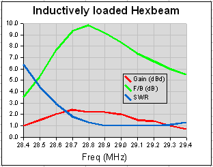
In addition to measuring F/B and SWR, I also built a linear half-wave dipole centred on 28.8 MHz so that I could make a direct comparison of the two antennas' forward gain. The results are shown in the chart on the right.
The figures measured are very close to predicted values. F/B peaks at just below 10dB, the Forward Gain peaks at about 2.3dBd, and the SWR exhibits the asymetric shape typical of loaded Hexbeams, including the Classic shape.
These results give a measure of confidence that the 2 inductively loaded designs described above should work as expected.