Hexbeam - how many bands?
Two frequently asked questions are: "Can I add 6m to my 5-band (20m-10m) Hexbeam ?", and "Can I extend my spreaders and add 30m/40m to my 5-band (20m-10m) Hexbeam ?". We might even consider doing both - a single rotatable antenna covering 40m thru 6m would be very attractive! However there are some pitfalls.
Firstly, the shape of the typical 5-band Hexbeam support structure results in barely-adequate vertical spacing between the 10m and 12m wires. Adding more bands makes a marginal situation worse, and it will likely prove difficult to get enough 10m/6m separation on a 20m thru 6m array, or sufficient 15m/12m/10m separation on a 40m thru 10m array, if the wires are simply allowed to take up their "natural" position in the stack. The situation can be improved by placing the wires at the required minimum separation, and then using "extension cords" from the wires to the spreaders. Another option taken by some constructors is to sacrifice a band - for example, removing 12m in order to accomodate 6m.
Secondly, there is the potential for unwanted interaction between bands which are harmonically related. The problem does not seem to be acute between one band and its second harmonic - for example 20m and 10m. However, a band at the third harmonic is more problematic as we will see.


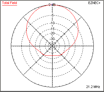
The chart on the right shows the azimuth plot of a 15m monoband Broadband Hexbeam in Free Space at its frequency of best F/B. It produces a Forward Gain of 5.04dBi and a F/B ratio of 25.2dB. Notice how the rearward response is very well controlled - there are no secondary lobes, and the high F/B is not the result of some narrow null at 180°. If we now stack a 40m Broadband Hexbeam 48" above the 15m wires we might expect some interaction because the 40m Driver and Reflector will likely resonate at 21MHz and become "parasitic re-radiators", just like any Hexbeam Reflector. Let's see what happens.
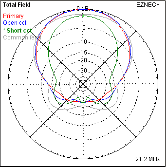
The second chart overlays the resulting 15m azimuth plots under three different conditions:
- The blue plot shows what happens if the midpoint of the 40m Driver is open-circuit. The Forward Gain has fallen fractionally to 4.97dB and the F/B is marginally worse at 23.8dB. More significant is the appearance of rearward sidelobes at about 120°.
- The Green plot shows the case where the midpoint of the 40m Driver is short-circuit - allowing it to become resonant in addition to the 40m Reflector. The Forward gain has fallen by 1.6dB to 3.44dBi, and the F/B has dropped to 22.2dB. The rearward sidelobes have increased significantly as a proportion of the forward power.
- Finally, the grey plot shows what happens if we parallel feed the 40m and 15m Drivers. The Forward Gain recovers marginally to 3.88dB, but the F/B has dropped significantly to 18.7dB and the rearward lobes have grown to the level where the Front/Rear ratio is now only 12dB. This should not be a surprise - in this configuration we are actively driving the 40m elements rather than having them respond parasitically.
- What the plots do not show is that the SWR under all three conditions remains quite acceptable - demonstrating yet again that low SWR is no indicator of how well an antenna is performing.
We reach the following conclusions:
- There is the potential for significant element interaction and azimuth pattern degradation between any band and its third harmonic such as 40m/15m, 30m/10m and 17m/6m combinations.
- If these combinations are to be used, they should not be driven by a common feedline. So, for example, on a 40m thru 10m array the 40m and 30m Drivers should be fed separately from the other elements.
- Pattern degradation can be reduced further by ensuring that the midpoint of the "unused" Driver "sees" a high impedance. This can be achieved by terminating the unsused feeder in an appropriate load, taking account of its electrical length.