Hexbeam common-mode current issues

Whenever a balanced antenna is fed with coaxial cable there is the potential for common-mode current to flow and cause problems. In extreme cases common-mode current can cause RFI when transmitting, local noise pick-up when receiving, and skewing of the antenna radiation pattern. The hexbeam is not immune from these problems - indeed, the multiband hexbeam provides a more than usual number of paths for common-mode current to flow.
The diagram on the right shows a close-up of a multiband hexbeam 20m feedpoint. Coax feedline from the transmitter is connected to the 20m driven elements, and another length of coax then interconnects the 20m driven elements with the 17m driven elements, and so on down the array.
Current flowing along the inner conductor of the coax feedline can only flow into the right-hand side of the 20m driven element, or onward through the interconnecting coax as a balanced differential-mode current to the 17m right-hand driven element. It will be balanced by an equal but anti-phase current flowing along the inside surface of the coax braid.
The balanced current flowing along the inner surface of the feedline braid can - depending on the relative path impedances - flow into the left side of the 20m driven element (green), back along the outer surface of the feedline braid towards the transmitter (red A), or along the outer surface of the interconnecting braid to the left-hand 17m driven element (red B). If the common-mode currents A and B are significant, the current flowing into the two halves of the 20m driver will be unbalanced and the antenna radiation pattern will become asymmetrical.
It is usual practice to place a common-mode choke on the coax feedline to reduce current A; but note that unless this choke is right at the 20m feedpoint there is still the potential for some common-mode current to flow. Rarely is any choking action taken to prevent common-mode current B from flowing.
To check out the practical effects of these common mode currents I made a series of 20m azimuth plots on my 5 band broadband hexbeam, placing "snap-on" type #43 ferrite chokes at various positions on the feedline and interconnecting coax. EZNEC modelling showed that the effects of the common-mode current and consequent driver current asymmetry are most pronounced on the rearward lobe of the azimuth pattern, so the following plots concentrate on that area. Full azimuth displays can be seen by clicking on the partial plots
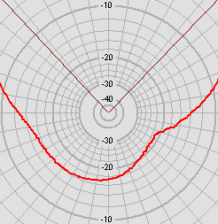 This plot shows the rearward lobe with no common-mode chokes installed. The asymmetry is very
clear - as much as 6dB difference in field strength between some corresponding azimuth angles.
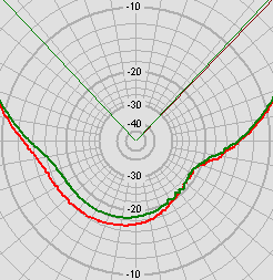 In this plot, the red trace shows the situation with no chokes present, and the green trace shows
the effect of adding a choke immediately below the hexbeam baseplate; there is a noticeably
improvement in symmetry.
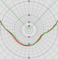 Here the red trace shows the performance with a choke below the baseplate and the green trace
shows the effect of moving that choke adjacent to the main 20m feedpoint. The improvement is not
so marked, but there is still a small improvement.
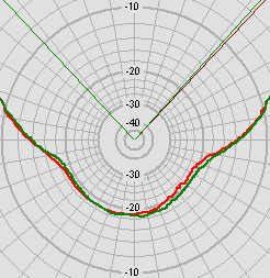 Here the red trace shows the performance with a choke adjacent to the main 20m feedpoint, and
the green trace shows the effect of placing an additional choke on the 20m/17m interconnecting
coax. Again there is a small but noticeable improvement.
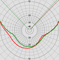 Finally, this plot contrasts the beam performance with no chokes (red trace) with the performance
when chokes are present both at the feedpoint and on the 20m/17m interconnecting coax.
It is unlikely that any of these asymmetrical patterns would be noticed in normal operation, however they do demonstrate that common-mode currents can flow both on the feedline coax and on the band-interconnect coax.
Adding a choke to the feedline does much to restore the symmetry, and is an easy and worthwhile step; as expected, there is a small advantage in placing that choke at the feedpoint rather than the baseplate. The ultimate symmetry is achieved by placing the choke at the feedpoint and adding chokes on the various band interconnecting coaxes (for those that don't have balanced line interconnects) - but that's probably just for "purists"!
Finally, please note that these measurements were all taken in the 20m band. The various common-mode paths will be electrically longer on the other bands, and so effects there may be more pronounced. If time permits in the future I will repeat measurements in the 10m band. It's also worth noting that the common-mode current flowing on the feedline is very dependent on the length of that feedline and where it is grounded - your situation my be quite different from mine.
You can find information on the performance of various common-mode choke designs on this website.