Classic Hexbeam - Measurements (Part 3)
My capability to make practical measurements on the Classic Hexbeam took a step forward when I constructed a 10m monoband test-bed antenna whose critical dimensions could be changed easily and which could be highered, lowered and rotated conveniently on a fibreglass telscopic mast. This page presents some of the measurements that I made on this test-bed. Unless otherwise stated, all antenna variants were constructed with #16 wire, Reflectors were dimensioned to be resonant mid-band, and Drivers were cut 2% shorter than the Reflectors.
1. End-spacing


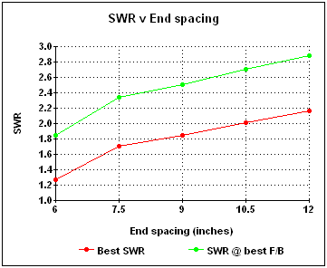
The spacing between the tip of the Reflector and the tip of the Driver was adjusted from 6" to 12" in 1.5" steps. For each value of end spacing the antenna F/B and SWR were measured over the frequency range 28 - 29 MHz with the antenna at a height of 20ft. The charts on the right present the results:
We note that:
- the frequency at which the F/B peaks increases steadily as the end spacing is increased;
- the peak F/B value increases with increased end spacing and is maximum at a value of 10.5", after which it begins to decrease. [ Caution: careful analysis of the azimuth pattern with an end spacing of 10.5" shows the 26dB F/B is produced by a sharp null at the back of the beam; either side of this null there are significant sidelobes which would be the limiting factor in rejecting signals from the rear. The Front-to-Rear figure becomes 19dB when these sidelobes are taken into account as shown in the dotted curve.];
- the frequency band over which the F/B exceeds 10dB is about 400 KHz for all end spacings;
- smaller end spacings tend to produce better SWRs;
- the ratio (SWR @ best F/B)/(Lowest SWR) lies between 1.3 and 1.5 for all end spacings;
- these results are exactly as predicted by the analysis presented on the Classic Hexbeam - In depth page.
Conclusion:
1. End spacings between 7.5" and 9" represent a good compromise between F/B
performance and SWR.
2. On a monoband design where the SWR could be improved by external matching components, the
end spacing might usefully be increased to 10.5" for improved F/B performance.
2. Beta matching


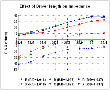
The length of the Driven element was reduced in 1 inch intervals whilst keeping the end spacing (8") and Reflector length constant; the antenna was up at 20 ft. At each step the Resistive and Reactive components of the feedpoint impedance were measured and are shown below in the chart on the left. Please note that the Reflector was shortened slightly before this set of measurements was taken - this raised the frequency of best F/B to about 28.75MHz.
We note that:
- shortening the Driver has resulted in a higher Resistive component of feedpoint impedance;
- shortening the Driver has resulted in an increasingly negative Reactive component of feedpoint impedance;
- when the Driver is 3.7% shorter than the Reflector (the blue traces) the impedance is [22 - j21] at the frequency of best F/B, making this a good candidate for Beta matching as predicted on the Classic Hexbeam - In depth page.
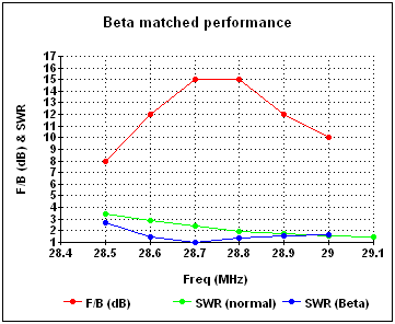
To confirm the utility of Beta matching, an inductor of about 270nH (Xl=50 Ohms) was added in parallel with the feedpoint. SWR and F/B measurements were then made across the band. The results are shown above in the right hand chart.
We note that:
- F/B performance has not changed as a result of adding the inductor;
- there has been a noticeable improvement in SWR. It is now lower than 2:1 across the F/B>10dB bandwidth of the beam, and it is lowest where the F/B is best.
Conclusion:
Beta matching is an simple and effective way of improving the SWR of a
monoband Classic Hexbeam
3. Effect of height on SWR

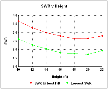
The antenna was raised from a height of 10ft to 22ft in 2ft steps. At each height the lowest SWR, and the SWR at best F/B, were measured. Results are plotted in the chart below.
We note that:
- SWR improves as the height is increased up to 18ft (approx a half-wavelength), after which it begins to deteriorate;
- the ratio (SWR @ best F/B)/(Lowest SWR) lies between 1.4 and 1.6 for all heights.
Conclusion:
Height has a significant effect on the SWR of a Hexbeam; best SWR occurs at a
height of about a half-wavelength.