Amateur Radio (G3TXQ) - Cobweb Antenna
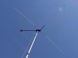
During recent range testing of a hexbeam I needed a horizontally-polarised resonant antenna covering 20m thru 10m which could be assembled and disassembled quickly and easily. The cobweb antenna meets the requirement nicely - it comprises 5 parallel dipoles bent into a square shape and mounted on a support structure made of fibreglass poles. The turn radius is a very compact 6.25ft. Computer modelling of this arrangement shows that one result of bending the dipoles is that the antenna is close to being omnidirectional in azimuth, with a Free Space eccentricity of about 4dB; a less attractive result is that the feedpoint impedance drops to around 12 ohms at resonance.
The commercial CobWebb antenna marketed by Steve Webb (G3TPW) - and most of the home-made derivitives - overcome this problem by using folded-dipoles constructed from Figure-8 twin lead as the elements. This raises the feedpoint impedance by a factor of 4 and provides a good match to 50 ohm feedline; the feedline is usually coiled to form an air-cored common-mode choke close to the feedpoint.
However, the folded dipole approach to matching has some disadvantages:
- The use of twin lead adds to the weight of the antenna
- A shorting link has to be placed at a position along the folded dipole, determined by the differential-mode velocity-factor of the cable. Variations in cable insulation can mean that the dimensions which work for one constructor may not work for another.
- Ideally, the shorting link position should be adjusted as part of the initial antenna tuning - something which is not easy to do. The folded dipole page on this web site looks in depth at the postioning of the shorting link.
- The "scramble-wound" air-cored balun often installed within the terminal box may not provide much choking impedance unless the dimensions and winding style are carefully controlled
- The use of twin lead makes it a little more difficult to assemble and disassemble the antenna if, as I do, you prefer to store the wires separately


The alternative arrangement I used was to combine the impedance transformation and balun functions into a 1:4 Guanella current balun mounted in the terminal box. This allows single-wire elements to be used, which simplifies assembly and tuning. The 1:4 balun comprises two 1:1 baluns wound with 8 turns of coax on a FT 140-61 ferrite toroid; the two baluns are then connected in series at the 50 ohm feedline end, and in parallel at the antenna end. The coax needs to have a characteristic impedance of 25 ohms - something which is not easily available; so each balun is actually wound with two 50 ohm coaxes which are connected in parallel at each end - inner to inner, braid to braid. Click on the photos on the right for enlarged pictures, and see the bottom of this page for more construction details.
I measured the loss of the Guanella balun between 14MHz and 30MHz; it varied between 0.1dB at 14MHz and 0.14dB at 30MHz - that's less than the loss in a coiled-coax balun comprising 6ft of RG-58! When terminated with a 12.5Ω load, the input VSWR varied from 1.06:1 at 14MHz to 1.1:1 at 28MHz.
The support structure is constructed from fibreglass tubing, and the wires are held in place by threading them through a tie-wrap loop which is itself tie-wrapped to the tubing; a stainless sheet metal screw driven into the tubing stops any tendency for the loops to slide inwards. The wires are terminated in solder tags which fit over 4mm bolts screwed through the terminal box. The ends of the dipole elements are connected to spacer cords (approx 6" long) using the brass inserts from plastic connector blocks; this arrangement allows any slack to be taken up easily by releasing the srews and sliding the wires through the inserts. The inner 'X' of the support structure comprises two 34" lengths of 0.75" OD tubing. A 66" length of 0.5" OD tubing then slots into each arm of the 'X' to an overlap depth of 7.5", giving a total diagonal length of 151". The rod supporting the balun box is a 42" length of 0.75" OD tubing. The wire tension keeps the whole assembly in place; this arrangement allows the antenna to be assembled and broken down very quickly. The following photos show the general idea:
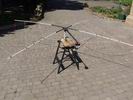
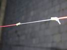
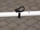
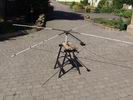
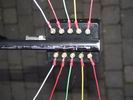
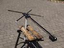
The following table lists the wire dimensions that were used each side of the feedpoint, the distance from the centre of the structure to the wire corner, the minimum VSWR, the 2:1 VSWR bandwidth, and the 3:1 VSWR bandwidth, for each of the five bands. Please note that the wire used was PVC insulated with an outside diameter of 2mm and a conductor diameter of 1mm; dimensions will vary slightly if you use different wire.
| Band | Wire length | Centre-to-corner length | Minimum VSWR | 2:1 bandwidth | 3:1 bandwidth |
| 20m | 201" | 72.25" | 1:1 | 208kHz | 362kHz |
| 17m | 157.5" | 56.75" | 1:1 | 170kHz | 299kHz |
| 15 | 135" | 48.25" | 1:1 | 167kHz | 293kHz |
| 12m | 114" | 40.25" | 1:1 | 156kHz | 271kHz |
| 10m | 100.5" | 34.75" | 1.2:1 | 184kHz | 337kHz |
SWR performance
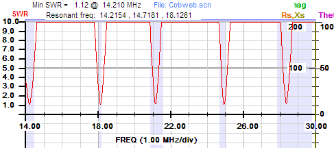
Here's a SWR plot measured at 25ft above ground. Please note that the SWR is referenced to the coax connector on the balun box; in practice the SWR bandwidth will be better than that shown because of losses in the feedline.
Balun Construction
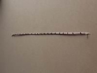
Some folk have had difficulty visualising the balun construction, so here are more details; click on the thumbnails for higher resolution photographs.
Cut two 510mm lengths of RG316 miniature coax (or RG174 if you do not intend running more than 100W). Trim the four ends to form short pigtails. Lay the two coaxes alongside one another and connect centre-to centre and braid-to-braid at each end. Although not strictly necessary, I find it helps keep things neat if you slide a few narrow pieces of heat-shrink tubing over the coaxes to keep them together. You have now created a single transmission line with a Characteristic Impedance of 25 Ohms
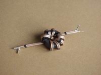
Now wind 8 turns of this twin cable onto a FT140-61 toroid to form a 1:1 Choke. The “crossover” winding is not an electrical requirement - it's just an easy way to get the coaxes to emerge at opposite ends of the ferrite core. Use a couple of plastic tie-wraps to hold the coax to the core at each end.
Now repeat all of the above steps to form a second 1:1 Choke.
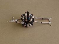
Now bind the two 1:1 Chokes together - again, I used a couple of plastic tie-wraps. Ensure that the two Chokes are aligned - i.e. the coaxes emerge at roughly the same positions
At one end of the assembly (left side of the 'photo) connect the coaxes in parallel: braid-to-braid, inner-to-inner; this is the end which connects to the antenna elements. At the other end of the assembly (right side of the 'photo) connect the coaxes in series: braid from one Choke to inner of the other; this is the end which connects to the SO239 and the feedline, using the remaining braid and inner.