Amateur Radio (G3TXQ) - G5RV Antenna
Few antennas polarise opinion as much as the G5RV - it seems you either swear by it or swear at it! The purpose of this article is to present a few technical facts about the antenna and allow the reader to judge whether or not it might be useful for them.
A. What is a G5RV?

Ask this question on one of the Internet Ham Radio discussion forums and you will almost certainly get a diversity of opinion. The problem partly lies with Louis Varney (G5RV) himself who variously described the antenna as having: a matching section of open-wire line, or 300 ohm line; a feeder comprising 50 ohm coax, 80 ohm coax, 75 0hm twin-lead, or no feeder at all; a balun, no balun, or an HF choke!
For the purposes of this discussion we shall assume that the antenna comprises:
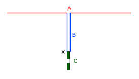
- A centre-fed dipole which is three half-waves long on 20m - shown red (A) in the diagram
- A ‘matching section’ of 300 ohm ladderline an electrical half-wave long on 20m - shown blue (B) in the diagram
- A length of 50 ohm coax of unspecific length - shown green (C) in the diagram
- The need for a balun at the ladderline-to-coax junction - point X - is discussed later
B. What bands does it cover?
Again you will find a wide range of opinions. There are those who claim that Varney only ever intended it to be a monoband 20m antenna, and those (often commercial antenna suppliers) who claim that it is an ‘all-band’ 80m thru 10m antenna. Certainly Varney discussed its performance on all bands 160m thru 10m (including the WARC bands), so it seems likely he thought of it as something other than a monoband antenna.
| Band | Best VSWR | Worst VSWR |
| 160m | >100 | >100 |
| 80m | 3.2 | 12.6 |
| 40m | 4.9 | 5.9 |
| 30m | 48 | 49.5 |
| 20m | 2.5 | 3.7 |
| 17m | 32.1 | 33.6 |
| 15m | 6.1 | 12.9 |
| 12m | 3.6 | 4.6 |
| 10m | 51 | 59.6 |
Let's model a G5RV in EZNEC and look at the feedpoint impedances. We will assume the dipole is built with #14 bare copper wire at a height of 30ft over average ground, and that the matching section is 300 ohm ladderline with a velocity factor of 0.9 and a loss of 0.2dB/100ft at 30 MHz. In building the model we firstly adjust the length of the dipole to be resonant at 14,150kHz, and then adjust the length of the matching section to be an exact half-wave at this frequency; we find the dipole needs to be 103.25ft long and the matching section 31.2 ft long (34.7ft * Vf).
The table on the right lists the worst and best 50 ohm VSWRs presented at point X for each amateur band. These are close to the VSWRs that would be seen by a transceiver if a very short length of low-loss coax were used. We notice that:
- On no part of any band does the VSWR fall below 2:1 - a typical limit for a modern solid-state transceiver
- All of 20m, and parts of 80m and 12m, have a VSWR below 4:1 - a typical limit for a modern transceiver with built-in auto tuner
- 80m, 40m, 20m, 15m, and 12m exhibit moderate VSWRs which should be within the matching range of an external tuner, and for which the losses in a short length of good-quality coax would likely be acceptable
| Band | Best VSWR | Coax loss |
| 160m | 20.7 | 20dB |
| 80m | 2.8 | 0.8dB |
| 40m | 3.3 | 1.9dB |
| 30m | 8.2 | 7.7dB |
| 20m | 2.0 | 1.5dB |
| 17m | 5.5 | 7.8dB |
| 15m | 3.3 | 3.1dB |
| 12m | 2.4 | 2.4dB |
| 10m | 4.8 | 10.5dB |
In an attempt to improve these VSWR figures, some commercial vendors supply the antenna with a long length of relatively lossy coax feeder, claiming (rightly) that this length is important to the working of the antenna. Let's run our model again with 70ft of RG58 coax between the ladderline and the rig. The table on the right shows the new VSWRs and the losses in the coax. We see that:
- 20m is now just about usable without any sort of tuner, at a cost of 1.5dB loss
- 80m, 40m, 20m, 15m and 12m would likely be within range of a built-in auto-tuner but we would have to accept losses over 3dB (for 15m)
- All bands 80m thru 10m would be within the matching range of a good external tuner, but the losses on 30m, 17m, and 10m would produce mediocre performance
- 160m is unusable [Varney only ever suggested using the antenna on 160m as a top-loaded vertical with the ladderline wires strapped together and fed against ground]
| Band | VSWR range (EZNEC) |
VSWR range (Measured) |
| 80m | 10 - 3.1 | 8.8 - 3.1 |
| 40m | 5.7 - 4.9 | 6.2 - 5.6 |
| 30m | 18.3 - 18.5 | >10 |
| 20m | 4.4 - 2.6 | 4 - 2.3 |
| 17m | 13.4 - 13.2 | >10 |
| 15m | 3.2 - 6.3 | 2.8 - 4 |
| 12m | 1.8 - 2.1 | 2.0 - 2.0 |
| 10m | 14 | >10 |
Finally, this table compares VSWR measurements made on a real G5RV with EZNEC predictions. The antenna was mounted in an Inverted-V configuration with the apex at just 18ft; the ends were at a height of 6ft. A 1:1 current balun was in place at the base of the ladderline, and the coax section comprised approximately 18ft of RG213.
There is generally good agreement between the predicted and measured results - certainly close enough for most amateur requirements. The VSWRs are a little different from those in the earlier tables because of the low Inverted-V configuration. Despite this significantly different configuration, the conclusions about band coverage are no different.
We conclude that, from a matching perspective, the G5RV is far from being an all-band antenna. With low losses in the coax section, the antenna cannot be used on any band without some kind of tuner. To quote Varney: "The use of an unbalanced-to-unbalanced matching network between the coaxial output of a modern transmitter (or transceiver) and the coaxial feeder is essential. This is because of the reactive condition presented at the station end of this feeder, which on all but the 14-MHz band, will have a fairly high to high SWR on it". With a modern in-built auto-tuner, it's at best a 3-band antenna (80m, 20m, 12m). With a good external tuner it's probably a 5-band antenna (80m, 40m, 20m, 15m, 12m). Other bands can be brought within matching range by incurring losses in the coax!
Of course by using a good external tuner and avoiding the coax section by bringing the ladderline all the way to the shack, losses will likely be acceptable on all bands 80m thru 10m ......... but is the antenna then a G5RV or simply a 102ft multiband doublet? Given that it was one of the feed systems described by Varney in his original 1958 article, perhaps it still is a G5RV!

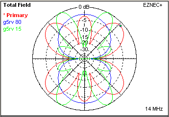
Like any multiband doublet the G5RV exhibits a different azimuth response on the various bands. By way of example, the diagram on the right shows the Free Space 80m response (blue), the 20m response (red) and the 15m response (green). On the lower frequencies the azimuth response is two lobes, each broadside to the antenna. As the frequency increases the response becomes more complex with multiple lobes and nulls. These features become less pronounced when the antenna is modelled above real ground, but nonetheless nulls up to 20dB deep are possible and it is worth taking account of them when planning the orientation of the antenna.
C. Balun or no balun?

It is good engineering practise to fit a 1:1 current balun at any coax/balanced transition in an antenna system; it helps prevent common-mode currents on the outside surface of the coax braid which may cause "RF in the shack" problems when transmitting and local noise pick-up when receiving. Varney advocated a balun in his original article, but in his 1984 Radio Communication article he changed his mind because he felt that the reactive loads could result in heating of the windings and saturation of its core. Even then he advocated a "coaxial cable HF choke".
With modern ferrite materials, and our better understanding of balun characteristics than in Varney's day, there is no reason not to include a ferrite-cored 1:1 Guanella balun at the ladderline/coax interface.
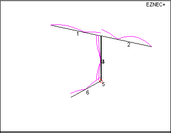
The diagram on the right shows what can happen if you don't include the balun; it is an EZNEC model of a G5RV antenna system. Wires 1 & 2 represent the antenna, wires 3 & 4 the vertical ladderline section, and wire 6 the coax section. The purple lines show the current distribution along the wires.
Notice that:
- The currents in the two dipole legs are unequal; this will cause "skewing" of the azimuth patterns
- The currents in the two ladderline legs are unequal; this will cause radiation from the vertical section on Tx
- There is considerable common-mode current flowing on the coax - coax which ends up close to the radio and other household equipment; this can cause RFI problems on Tx, and on Rx noise from that equipment can be injected at the coax/ladderline junction

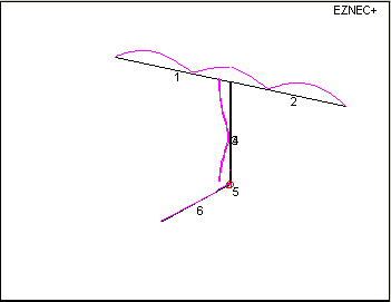
Now see how the situation improves when we include a 1:1 balun (or common-mode choke) - the currents in the two dipole legs and the two ladderline legs are well-balanced, and there is negligible common-mode current on the coax.
D. Can we do better?
| Band | Best VSWR | Worst VSWR |
| 160m | >100 | >100 |
| 80m | 8.3 | 18.8 |
| 40m | 1.1 | 1.4 |
| 30m | 87 | 89 |
| 20m | 1.2 | 3.2 |
| 17m | 1.4 | 1.6 |
| 15m | 80 | 90 |
| 12m | 1.2 | 1.4 |
| 10m | 1.5 | 9.7 |
Brian Austin ZS6BKW/G0GSF searched for combinations of antenna length and feedline length which would provide a reasonable match to 50 ohms on a number of HF bands; he was succesful - he found that an antenna 93ft long fed with 39.8ft of 400 ohm ladderline (Vf=0.9) provides a reasonable match on five bands. The table on the right shows the best and worst VSWRs of this antenna system on each HF band modelled at a height of 30ft above average ground.
The antenna would be usable on all of 40m, 17m and 12m without any tuner, and much of 20m and 10m. Perhaps its greatest disadvantage is that it does not cover the popular 80m and 15m bands without a tuner.
When LB Cebik analysed the G5RV and variants, he concluded: "Of all the G5RV antenna system cousins, the ZS6BKW/G0GSF antenna system has come closest to achieving the goal that is part of the G5RV mythology: a multi-band HF antenna consisting of a single wire and simple matching system to cover as many of the amateur HF bands as possible. From 80 to 10 meters, Austin's system provides an acceptable match on 5 out of the 8 bands under most conditions without an antenna tuner. This is the best result that has been achieved of any of the systems that has come to my attention."